5x proof, 4-20 mA output, Blender Pressure Measurement
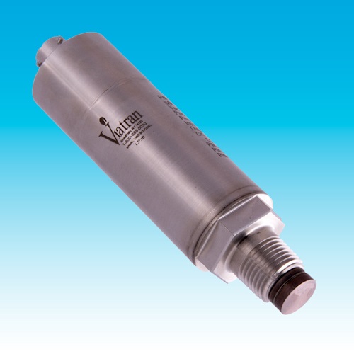
The Model 570 Flush Tip – Zero Cavity design offers an Isolated sensor assembly that virtually eliminates installation torque effect and is able to withstand pressure spikes up to 5x proof pressure and 20x burst pressure.
Features
![]() All Stainless Steel construction
All Stainless Steel construction
![]() Many Options available
Many Options available
High Overpressure Applications
![]() IP-67 Rated
IP-67 Rated
The Model 570 Flush Diaphragm Pressure Transmitter is designed to meet the rigorous demands placed on pressure transmitters used for well-servicing applications including manifold charge and high-pressure pump suction pressure measurements.
Features of the Model 570 flush diaphragm pressure transmitter include:
- Flush Tip Diaphragm (Zero Cavity Design)
- Patented* Solid Stainless-Steel Diaphragm Technology
- Isolated Sensor Design virtually eliminates torque effect
- Withstands 5 times Proof Pressure at 0-1,000 psis range
- Withstands 20 times Burst Pressure at 0-1,000 psis range
- High Accuracy (≤ +/-0.50% FSO)
- IP67 rating (Fully welded and sealed housing)
- Hazardous Approval Options Available
Minimizing the torque effect on the diaphragm has eliminated the need to adjust the instrument after installation.
The ability to withstand pressure spikes up to 5 times the 0-1,000 psis range extends the life of the transmitter when cavitation is a risk in the system.
The patented pressure sensor diaphragm technology has resulted in a very stable unit with the high performance and data integrity needed for blending in acidizing, cementing and fracturing applications.
*US Patent 9,851,272 B2
Full Scale Pressure Ranges: 0-100, 150, 160, 200, 250, 300, 400, 500,750, 1,000 PSIS
Accuracy (RSS): ≤±0.50% FSO (Includes BFSL, Hysteresis and Repeatability by RSS)
Compensated Temperature Range: 70°F to 170°F (21°C to 77°C)
Operating Temperature Range: -40°F to 185°F (-40°C to 85°C)
Storage Temperature Range: -40°F to 250°F (-40°C to 120°C)
Long Term Stability (%FSO): ≤±0.5% FSO per 6 months
Thermal Effect on Zero: ≤±2% FSO per 100°F Typical
Thermal Effect on Span: ≤±2% FSO per 100°F Typical
Output Signal: 4-20 mA
Supply Voltage: 8-28 Vdc
Power Supply Regulation: <±.05% FSO per volt
Load Impedance: 926 Ohms maximum at 28 volts DC
Circuit Protection: Reverse polarity protected, CE marked
RFI / EMI: CE EMC compliant as per IEC EN 61326-1 and EN 61326-2-3 Annex BB
Voltage Spike Protection: Withstand 1000 volt spike per EN 61000-4-5
Insulation Resistance: <5 nS
Response Time: <2 mSec for 10-90% of final value
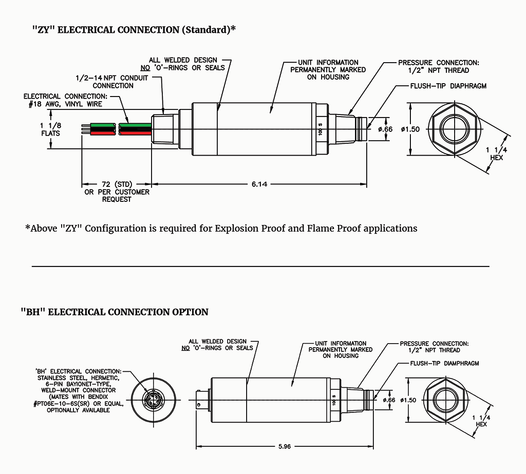
Electrical Connection: Bendix PT02E-10-6P, mates PT06E-10-6S (SR) (BH option)
Pin Outs:
Pin A + Power / Signal
Pin B – Power / Signal
Pin C No connection
Pin D No connection
Pin E AC Ground
Pin F No connection
Shell Case Ground
Standard Pressure Port: 1/2″ NPT (M)
Zero Effect from Installation: <±0.10% at 25 to 50 ft lbs
Proof Pressure: 5x
Burst Pressure: 20x
Wetted Materials: 15-5 PH and 304L Stainless Steel (Inconel 718 optional)
Weight: 8 oz. nominal
PRESSURE RANGES:
AM: 0-100 PSISFH: 0-6 BARS
AN: 0-150 PSISFI: 0-10 BARS
CA: 0-160 PSISFJ: 0-13 BARS
AP: 0-200 PSISFK: 0-16 BARS
AQ: 0-250 PSISFL: 0-25 BARS
AR: 0-300 PSISFM: 0-35 BARS
AT: 0-400 PSISFP: 0-60 BARS
AU: 0-500 PSIS
AY: 0-1,000 PSIS
ALTERNATE ELECTRICAL CONNECTIONS:
BH: Welded – 6 Pin bayonet shell size 10
PRESSURE CONNECTION:
VQ: 3/4″-16 UNF (M) per J1926-2
VR: G 1/2″ (M) per DIN 3852-11, Type E
VS: G ½ (M) per DIN 3852-11, w/ two “O” rings
PERFORMANCE OPTIONS:
DG: Improved Temperature Compensation ≤±1.0% FSO per 100°F (Typ.)
EA: Special Calibration Run
GA: Viton O-ring (for VQ, VR and VS Pressure Ports only)
GD: EDPM (Ethylene Propylene Diene Monomer rubber) O-ring (for VQ Pressure Port only)
NH: Customer Specified Marking
QK: Inconel 718 – for all wetted parts (Not available for AM (100 psis) range)


