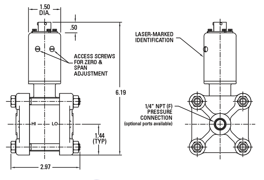
Low Range Differential Pressure, 1000 psi line Pressure
Viatran’s “74” Series differential pressure transducers/transmitters are extremely accurate and durable units, designed specifically for test applications. The variable capacitance sensing technology provides extremely high overpressure protection, and long range stability, as well as high accuracy of 0.15% BFSL.
Features
![]() High Accuracy
High Accuracy
![]() Many Option available
Many Option available
The Model 274 Differential Pressure Transducer measures pressure ranges from 5″ W.C. to 100 PSID and provides a 0-5 VDC signal.
All wetted surfaces, including flanges and diaphragms, are constructed of 316 stainless steel with a sealing Viton® O-Ring for excellent corrosion resistance.
A standard 1,000 PSI static line pressure and single side overpressure rating are featured with these transducers.
For applications that require a higher static line pressure rating, 3,000 PSI is available with optional flanges.
Model 274 also features an internal calibration circuit for easy field set-up, a quick disconnect electrical connection and external zero and span controls.
A special option called fast response enables the unit to accurately respond to changes in pressure in approximately one tenth of the standard time.
These features make the Model 274 ideal for most industrial test and flow applications.
Full Scale Pressure Ranges:
- 0-5, 10, 20, 50, 100, 300, 750″ W.C.D.
- 0-15, 50, 100 PSID
Nonlinearity (Best Fit Straight Line): ≤±0.15% FSO
Hysteresis: ≤±0.08% FSO
Repeatability: ≤ ±0.06% FSO
Full Scale Output (FSO): 5 Vdc at 70° F
Resolution: Infinite
Long Term Stability: ≤±0.1% FSO per 6 months
Zero Shift w/Line Pressure (%FSO/1000 PSI):
- 5” WC to 100” WC : ≤ 4%
- 300” WC to 100 PSI: ≤ 6%
Span Shift w/Line Pressure (%FSO/1000 PSI):
- 5” WC to 100” WC : 0 to -6%
- 300” WC to 100 PSI : 0 to -4%
Zero Shift After 1000 PSI Overload:
- Single Side: ≤± 0.1% FSO
- Alternate Sides: ≤±0.5% FSO
Compensated Temperature Range: 70°F to 170°F (21°C to 76°C)
Operating Temperature Range:
- 5″WC to 50″WC (0° F to +170° F)
- 100″WC to 100 PSI (-40° F to +170° F)
Storage Temperature Limits:
- 5″WC to 50″WC (0° F to +170° F)
- 100″WC to 100 PSI (-40° F to +170° F)
Temperature Effect on Zero: ≤± 2.0% FSO per 100° F
Temperature Effect on Span: ≤± 2.0% FSO per 100° F
Supply Voltage: 9 TO 30 Vdc
Power Supply Regulation: ≤±0.0001% FSO per Volt change over the supply voltage range
Output Signal: 0 to 5 Vdc
Output Loading: 3000 Ohms minimum
Current Draw: 3.8 mA
Zero Adjustment: ± 10 % FSO min. / ±20% FSO max.
Span Adjustment: ± 10% FSO min. / ±20% FSO max.
Calibration Signal: 80% of the FSPR, by shorting pins E & F
Calibration Signal Accuracy: ≤±0.1% of the stated value
Circuit Protection: Reverse polarity protected
Insulation Resistance: >1000 MegOhms to case ground at 50 Vdc and 70° F
Response Time: 10% to 90% FS (Faster response available with NF option.)
Electrical Connection: Bendix PT02E-10-6P, mates PT06E-10-6S (SR)
Pin Outs:
Pin A + Power
Pin B – Power
Pin C + Signal
Pin D – Signal
Pin E Calibrate
Pin F Calibrate
Wetted Parts: 316 Stainless steel and Viton O-Ring
Housing: 304 and 316 Stainless Steel with an Aluminum alloy, black zinc-cobalt plated electrical connector
Weight: 3.5 lbs. (6.5 lbs. with optional flanges)
Identification: Laser etched onto body
Pressure Connection: 1/4″ – 18 NPT female
Static Pressure: 1000 PSI maximum (3000 PSI – optional)
Proof Pressure: 1000 PSI single sided (3000 PSI – optional)
Burst Pressure: 1500 PSI (4500 PSI – Optional)
Diaphragm Displacement: 0.002 cubic inches at FSPR
Pressure Cavity Volume:
- Standard Flanges: 0.4 cubic inches
- Optional Process Flanges : 1.5 cubic inches
Fill Fluid: Dow DC200 Silicone oil
Mounting: May be supported by process piping or by optional mounting bracket
ELECTRICAL CONNECTION:
B ( ): Alternate electrical connector
PERFORMANCE OPTIONS:
DG: Improved temperature compensation to ±1.0% FSO per 100°F
DH: Special ranging
DK: Special shunt calibration setting
DM: Modified full scale output
DQ: Cleaning for oxygen service
EA: Special calibration run
GE: Buna ‘N’ O-Rings
NB: Alternate process flanges for increased pressure rating
NF: Fast response time
NH: Customer specified identification
NM: Alternate output signal (3mV/V)
ALTERNATE PRESSURE PORTS:
Y ( ): Alternate pressure ports
Note:
Application of some available options may affect standard performance.


